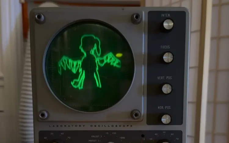
Heathkit IO-12
Trying to restore a vintage oscilloscope
ongoing serieswatch the series on YouTubeparts 1–7 so far, in order from part 1
the short version
the heathkit io-12 is a 1960s lab oscilloscope. heathkit sold it as a kit with an assembly manual, and this one is about sixty years old. inside there's a 5-inch crt and a row of vacuum tubes. i got it for $20, and it didn't work at all: no trace, nothing on the screen.
the series is me fixing it one fault at a time, and every fault was hiding the next one:
once it worked, i used it the way oscilloscope music does: in xy mode, stereo audio is a drawing. it played tennis for two, doom and bad apple. then everyone asked what bad apple sounds like, and part 8 is about that: the drawing is just a buzz, so i tried to get the song itself to draw the picture.
safety: this scope has lethal voltages inside, both mains and the crt's high-voltage supply (over a thousand volts). some of the measurements in these videos were taken live. don't copy them.
part 1: no trace
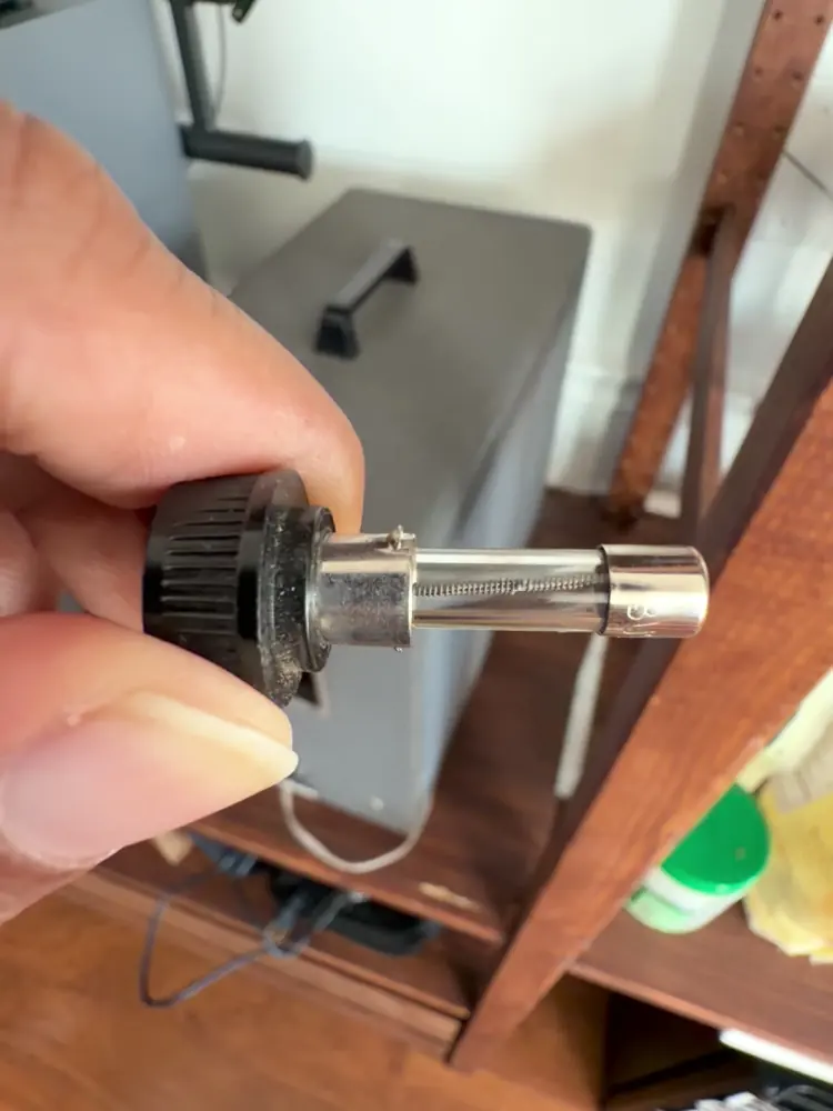
it powered up to nothing. no trace, no dot. the fuse holder on the back unscrews, and the fuse inside was blown.
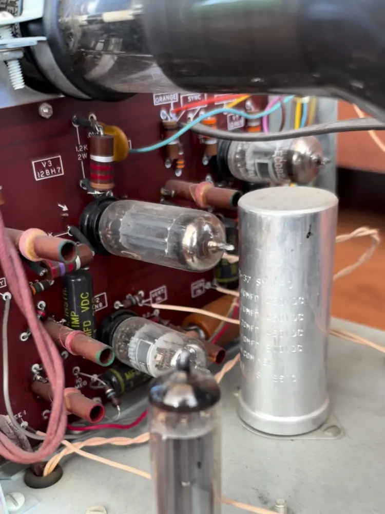
a new fuse would just hide the problem. fuses blow for a reason, so instead of swapping it and switching on again, the case came off: a 5-inch crt, and the tubes on a red circuit board.
watch part 1 · Why won't this old scope work?
part 2: the dim bulb tester
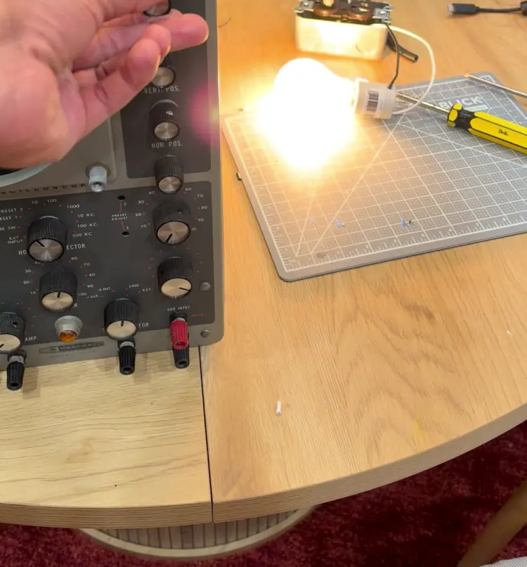
a dim bulb tester is a light bulb wired in series with whatever you're testing. if the thing is healthy, it only draws a little current and the bulb barely glows. if something inside is shorted, the bulb lights up and takes the hit instead of the fuse. mine is a lamp socket and an outlet in a metal box, with a 60 W bulb. a 60 W bulb is about 240 Ω when it's hot, so even a dead short can only pull about half an amp through it.
i tested it on a dremel first: the bulb lit up when the motor ran, so it works. then the scope went in, and the bulb stayed bright.
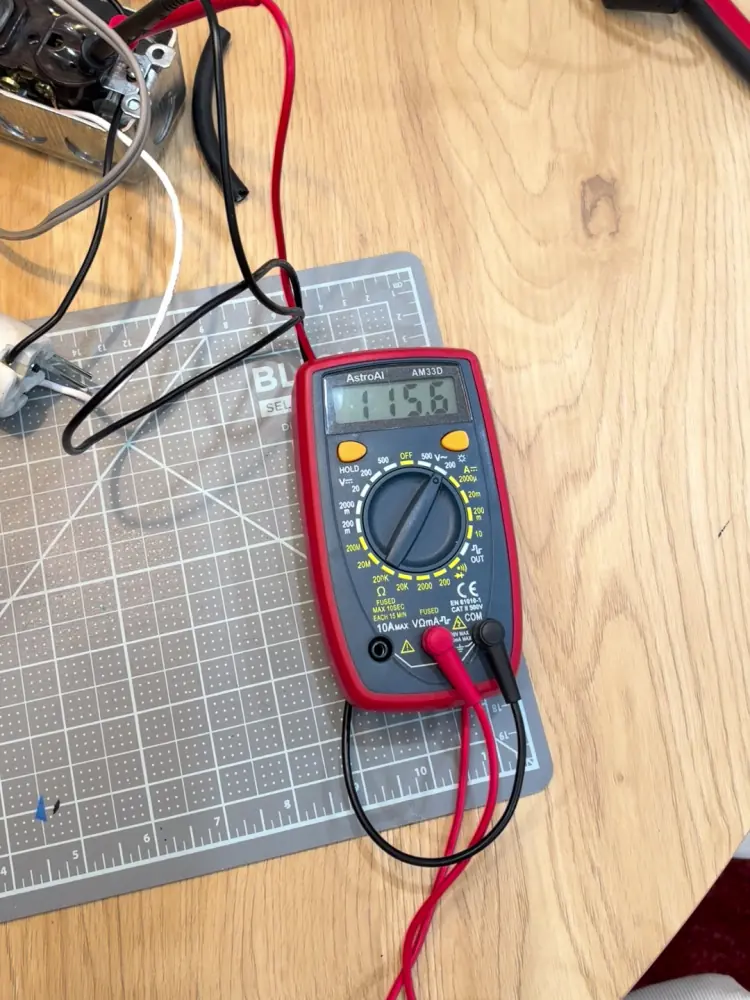
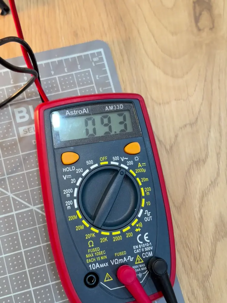
my meter read 115.6 V on the tester side and 9.3 V at the scope. the bulb was eating almost all of it, so there's basically a dead short in there. turning the scope's own power switch off made the bulb go dark, so the short is somewhere after the switch.
watch part 2 · The dim bulb tester
part 3: the leaking capacitor
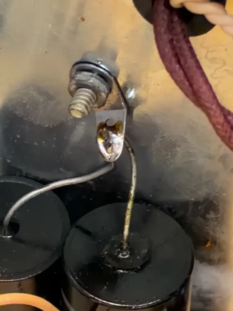
under the chassis, one of the old paper capacitors had goop leaking out of it: a puddle of tar around its lead and streaks down its label. old paper caps dry out and crack, the tar leaks out, and eventually they short. this one measured as a dead short. its label reads .1 MFD, 1600 VDC, and it sits in the supply that makes the crt's high voltage.
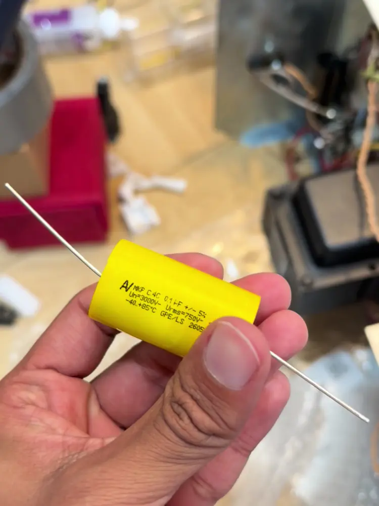
so i cut it out and swapped in a new one (0.1 µF, rated 3000 V), with some double-sided tape to keep it in place.
through the dim bulb tester, the bulb flashed and then went dim, which is what you want to see, and the pilot light came on. but straight from the wall: still nothing on the screen. with the lights off you could see that something was off: one of the vacuum tubes wasn't glowing like the others.
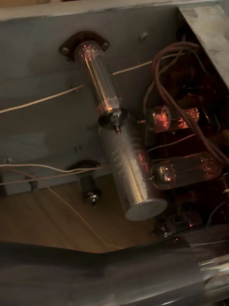
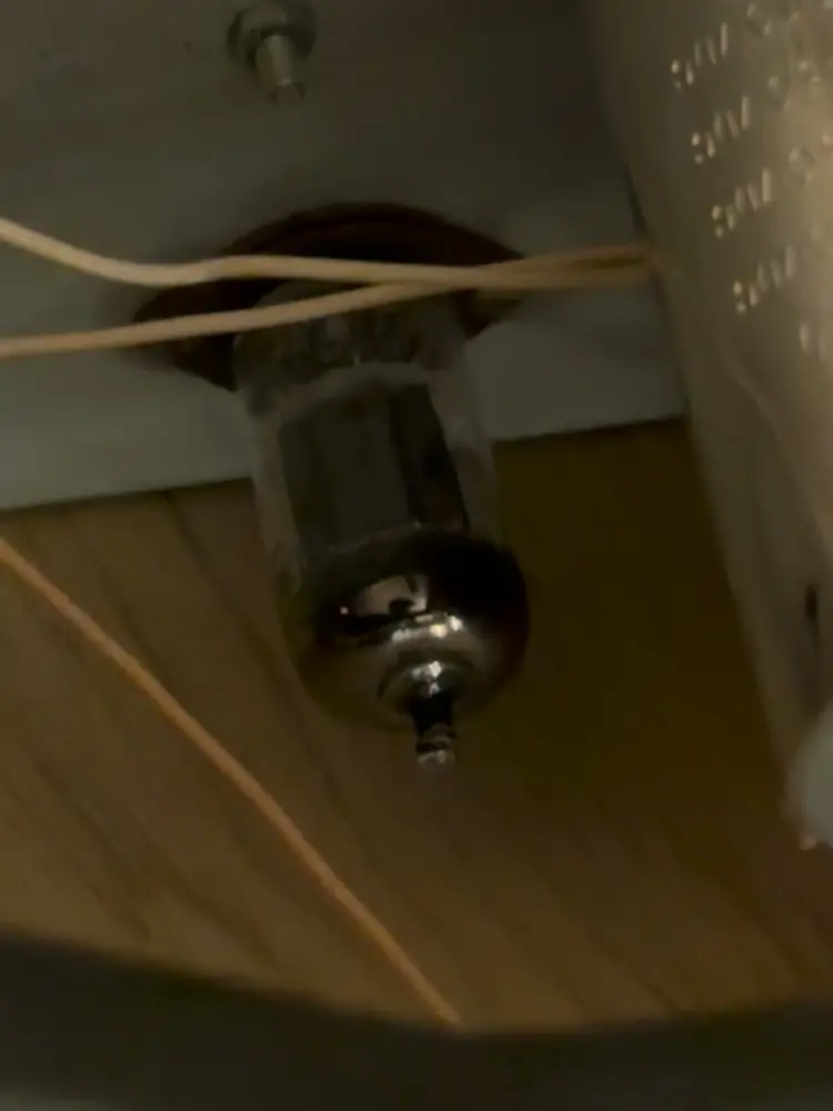
watch part 3 · The short, the fix, and the one dark tube
part 4: the wrong tube
the dark tube worked fine in another socket, so the tube wasn't dead. its own socket had basically no voltage: my meter read 0.4 V ac on the heater leads.
i followed the yellow wires back to the transformer and pulled up the schematic. they come from their own little winding and go to V9, which is supposed to be a 1V2: the rectifier that makes the high voltage for the crt, with a heater that runs on about 0.6 V. but someone had jammed a 12AU7 in there, which wants 12.6 V on its heater. on 0.6 V it never lights.
so i ordered a real 1V2 (it came with a nice thank-you note: thanks jim!), put it in V9, and after a bit of warming up, there's a dot.
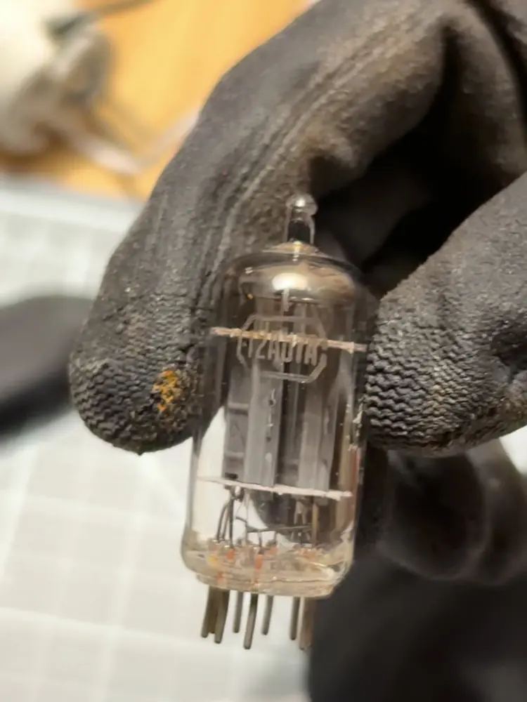
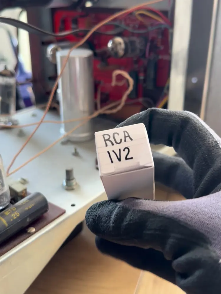
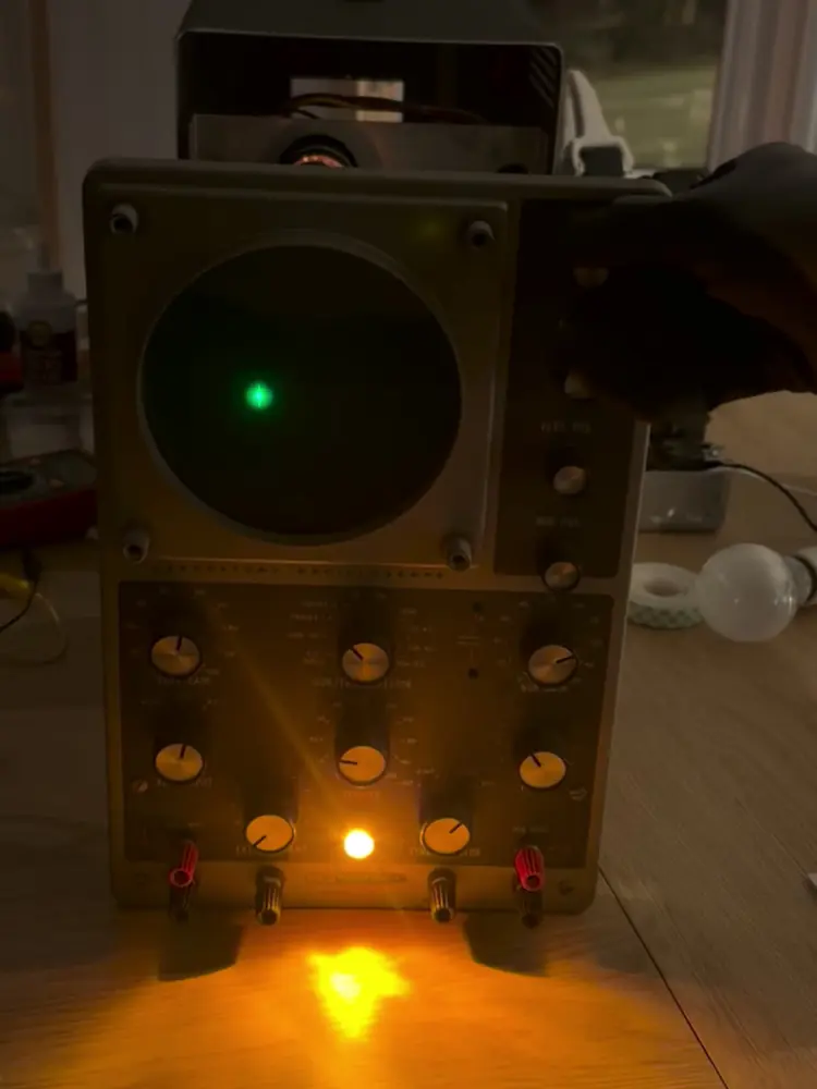
with my guitar plugged in, the dot reacted to the signal. but it drifted all over the place, it only ever stretched into a vertical line, and the horizontal frequency selector knob was completely stuck.
(the 0.4 V reading was taken live, on leads that sit right next to the high-voltage winding. again: don't copy this.)
part 5: only works sideways
a crt scope normally draws a graph: an oscillator inside sweeps the beam from left to right, over and over, while your signal moves it up and down. no sweep, and the whole signal piles up on one vertical line. that's what mine was doing.
i took it out of the case and started probing around, but couldn't find anything. then, with the scope tipped on its side, it all of a sudden started working: the actual signal from my guitar's pickup, on the screen. it works on either side. the second i stood it back up, it collapsed back into a line.
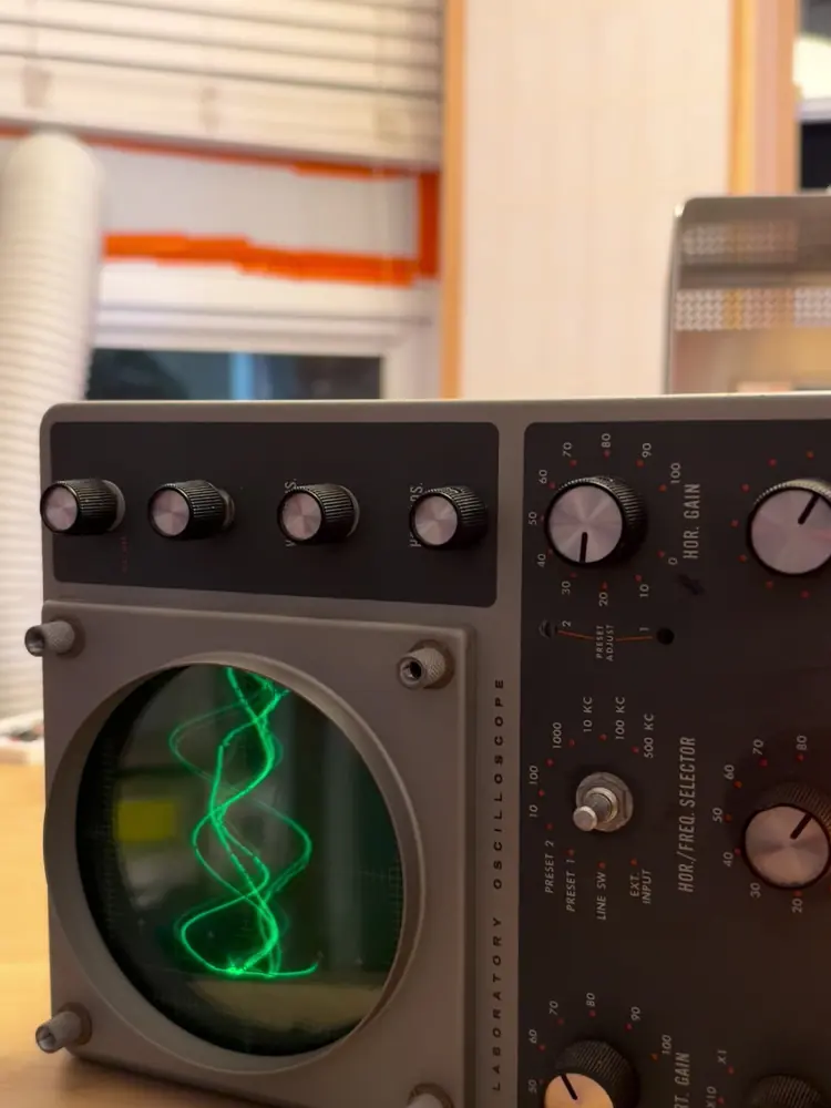
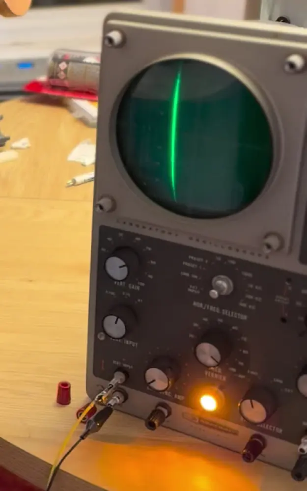
i suspected the stuck horizontal frequency selector knob, so i sprayed it with deoxidizer. still stuck. my best guess was that something inside it was just barely touching, and tipping it was just enough to connect. the good news: if it works sideways, everything else must be working. i just had to find one bad connection.
(the selector guess turned out to be wrong.)
watch part 5 · It only works sideways
part 6: a screw loose
you guys had a lot of theories: a loose tube socket pin, a bad solder joint, something loose inside, tap around in there with something that doesn't conduct. so i tried them. i pushed on every tube on the horizontal side while it was upright: nothing. i even tried it lying on its back: still nothing.
then, under the circuit board: this terminal strip is supposed to be screwed down to the chassis, which is ground. the screw (and its lockwasher) was just missing, and the eyelet was empty. when i poked the strip, the trace flickered on.
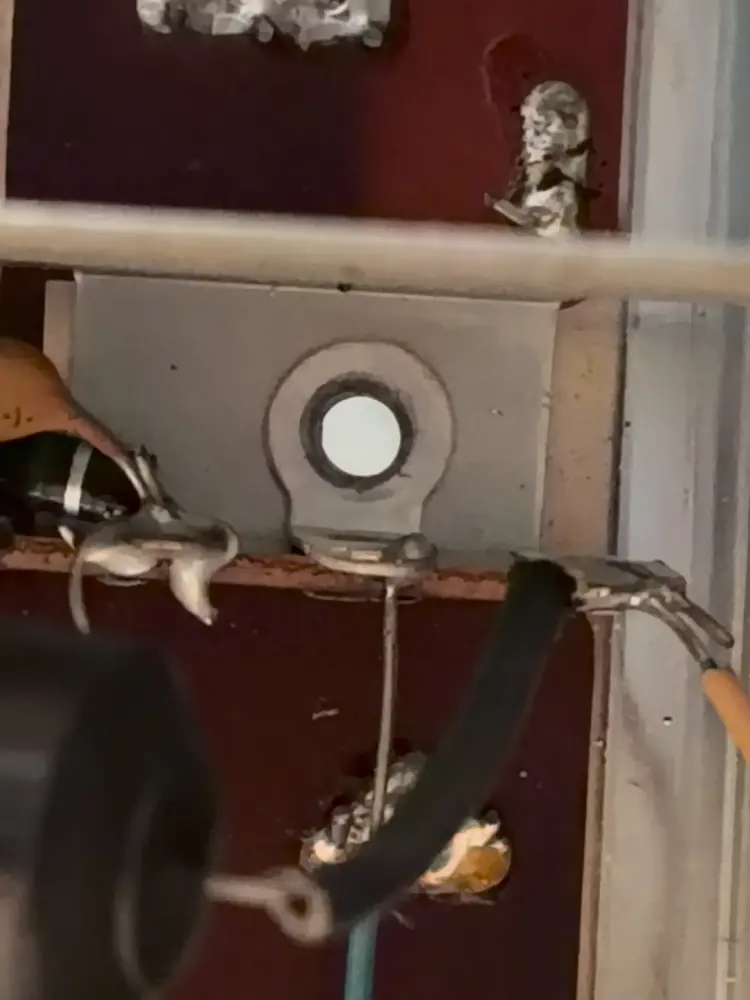
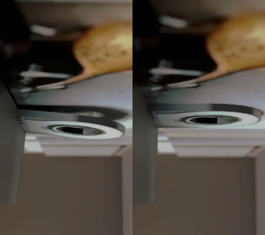
upright, the strip hangs just far enough away to lose contact. tip it on its side and it falls back against the metal. that strip is part of the sweep circuit, around the 6J6 tube (V4), so no ground means no sweep. the vertical amplifier grounds somewhere else, which is why i still had a vertical line.
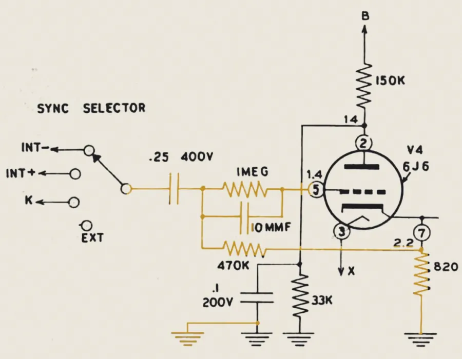
it's borderline impossible to get a nut on there without taking out the whole tube, so i soldered a jumper wire over to the next strip, which is grounded.
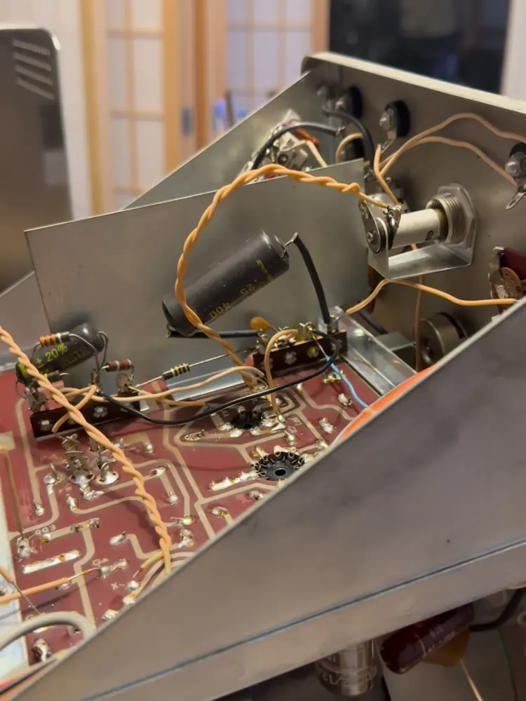
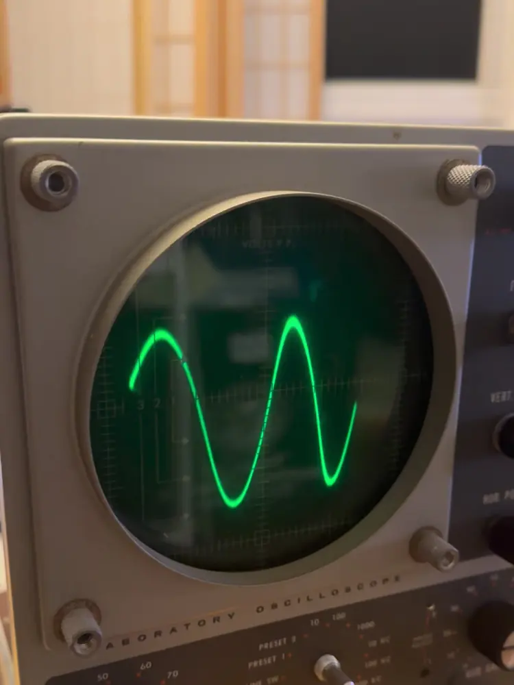
it works right side up. a tone generator on my laptop showed a 60 Hz square, sine, sawtooth and triangle wave, and then some music. one problem left: the frequency selector was still completely seized, so no xy mode yet.
watch part 6 · It finally works upright
part 7: xy mode, and bad apple
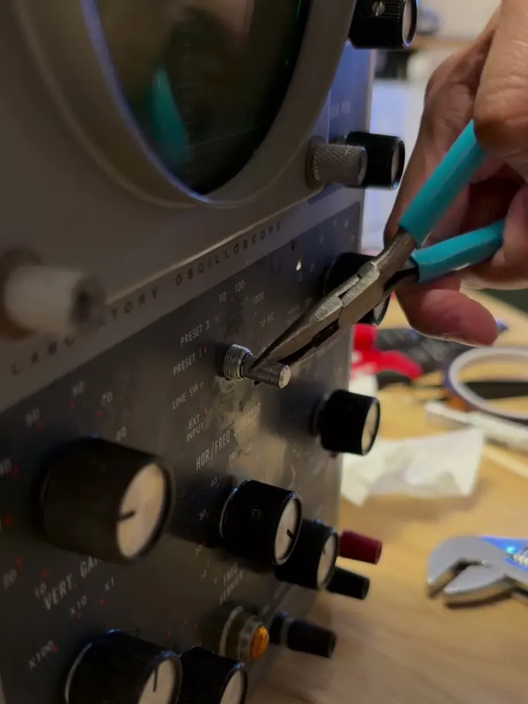
after six parts, i finally managed to turn that stuck knob: wd-40 at the front panel and under the chassis, an adjustable wrench on the panel nut, then pliers (and in the end wire strippers) on the bare shaft. it's still very stiff, but it reaches EXT INPUT now. in that position HOR INPUT moves the beam sideways instead of the sweep, and that's xy mode.
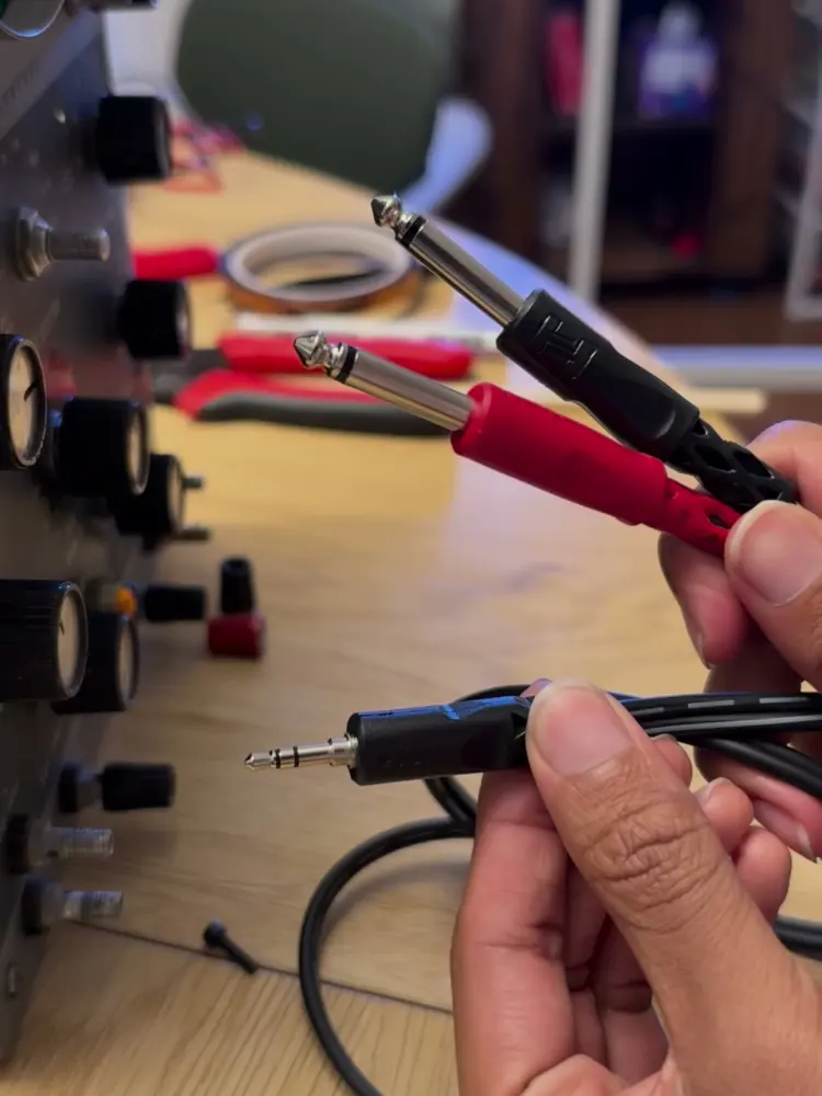
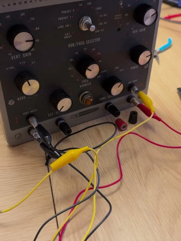
my laptop's headphone output goes through a stereo splitter: the left channel goes to HOR INPUT and the right to VERT INPUT, each with its ground on that input's GND post. so the left channel of the audio moves the beam on the x axis, and the right channel controls the y.
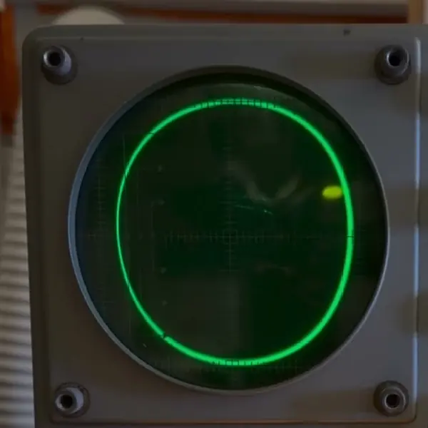
if they're both playing the same sine wave in sync, you get a line. offset one by a quarter of a cycle and you get a circle. if you design the waveforms the right way, you can draw anything. (i made the circle round with HOR GAIN and VERT GAIN, and centred it with HOR POS and VERT POS.)
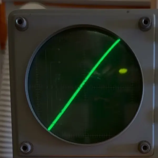
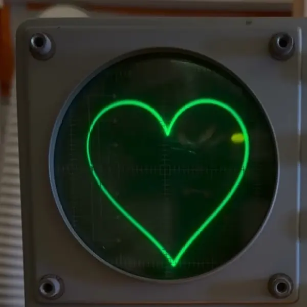
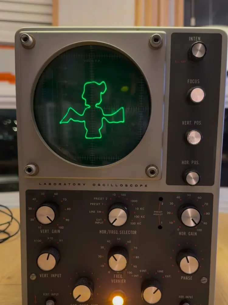
of course, i had to try some games. tennis for two (1958, one of the first video games, and it ran on an oscilloscope): a court line, a short net and a ball in parabolic arcs, with two automatic players rallying. doom: a first-person wireframe of the first level, built from the real shareware map data, with the shotgun outline bobbing along. and bad apple: every outline of every frame of the video, redrawn 60 times a second.
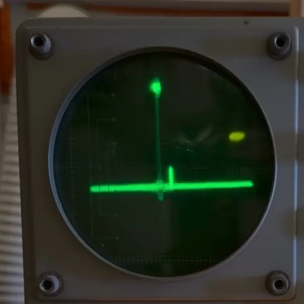
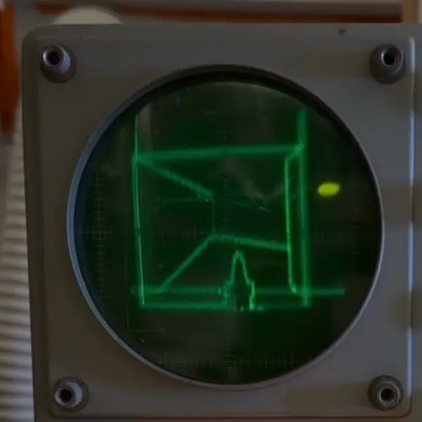
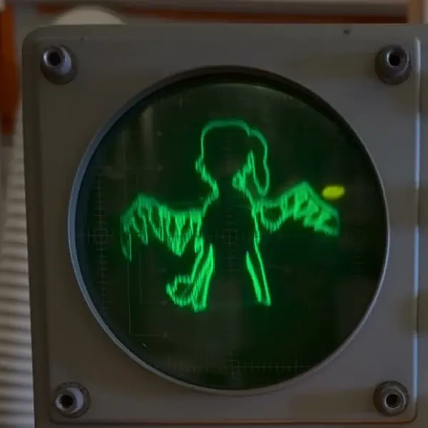
for bad apple, my encoder takes every frame, finds the outline of every shape, simplifies it, picks an order to draw them in, and moves the beam at a steady speed so the brightness stays even. it also pre-compensates for the sound card's filter and the scope's input coupling, which would otherwise round off the corners and make the picture sag. 99.86% of the 6572 frames get fully drawn.
one catch: after about six minutes powered on, the trace gets really jittery and noisy, and once it cools down it's fine again. the cause isn't confirmed. my best guesses: tired filter capacitors, a solder joint or tube that cuts out when it's hot, or carbon resistors that have drifted. it's part of why i might finally need to recap it.
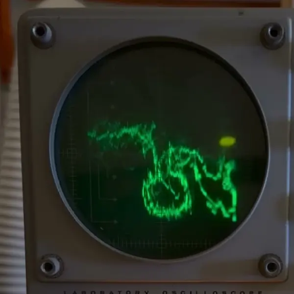
watch part 7 · XY mode, and Bad Apple
part 8: what does it sound like?
in part 7, the sound in the video was the real song, laid over the top. so a lot of you asked the obvious question: ok, but what does the drawing itself sound like?
the buzz
it sounds like a buzz. i know, not great.
the part 7 signal traces the picture sixty times a second, and anything that repeats is a note: sixty times a second is a 60 Hz note, with a stack of harmonics on top. it isn't even in tune. 60 Hz falls between B♭1 (58.3 Hz) and B1 (61.7 Hz), so it's out of tune with everything.
idea 1: melody drawing
the first idea is to trace the picture at whatever note the melody is on, a couple of octaves down so it has time to draw. each trace lasts exactly one period of the note, so one retrace is one note, and the picture plays the tune. BilliumMoto has a great writeup on doing this (he even gets chords out of it).
the catch: a higher note leaves less time to draw. with the vocal melody two octaves down (D2 to E♭3), the low notes have plenty of time, but by around 185–205 Hz every frame has to be drawn coarser. i also tried following the song's bassline instead, folded into 55–95 Hz so there's always time to draw.
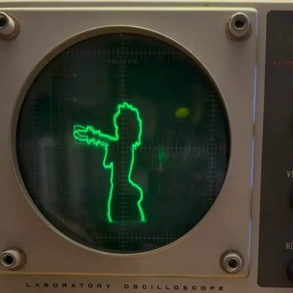
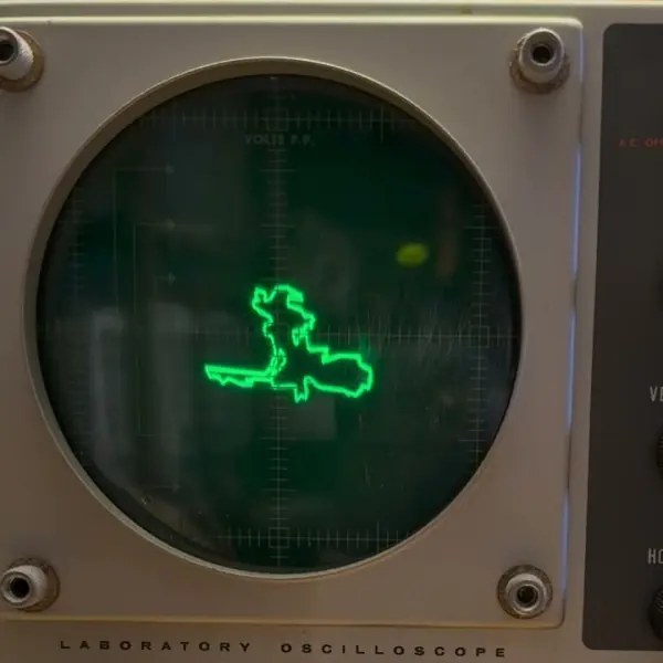
it's slightly better, but it's still basically a buzzer playing bad apple.
idea 2: make the song draw
so let's flip it around: instead of making the picture play music, let's make the actual song draw the picture. here's the original song going straight into the scope. it's a blob: the left and right channels of a song are mostly alike, so the beam stays near the diagonal.
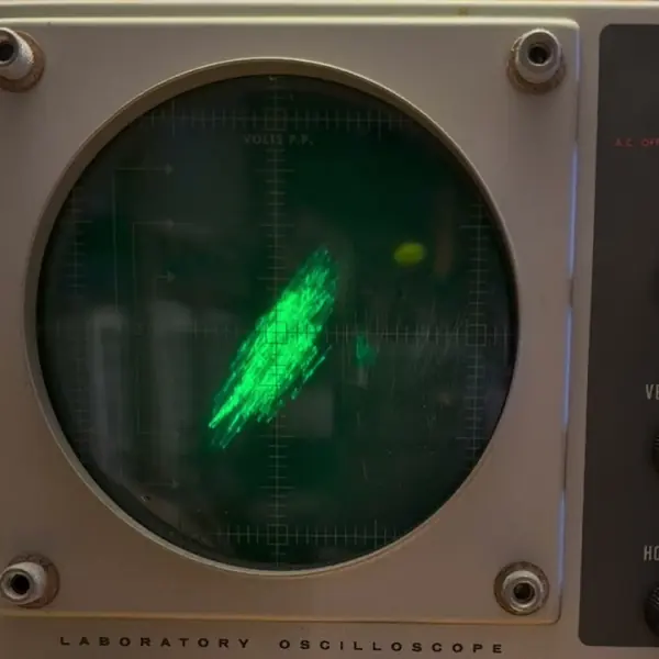
the trick is that every sound can be split up into a stack of pitches, and your ears mostly care how loud each one is, not exactly when each one starts. so if i slide one of them in time, the wave looks completely different, but it sounds pretty much the same. that's what an all-pass filter does: every pitch comes out just as loud, it just gets shifted in phase.
so the question becomes: how far do i slide each pitch, at every moment, so the beam traces the picture? the video starts with a rigged demo: 32 pitches picked so they can form the picture, scrambled, then slid back. every pitch's level stays within 0.002 dB the whole time, and a pile of scrambled pitches slides into bad apple.
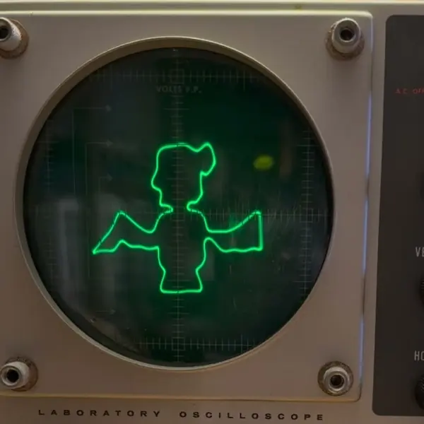
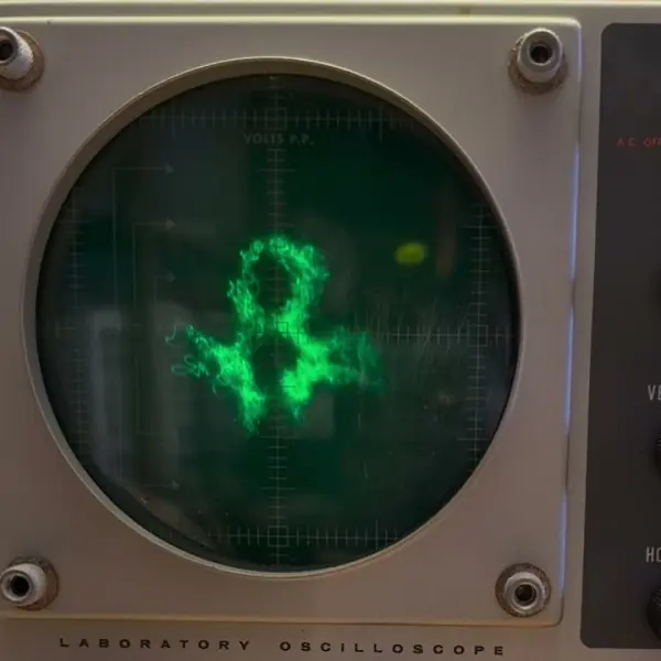
that one was rigged. with the real song, my encoder splits it into 64 bands and slides each one, every frame, and it turns the left and right channels by different amounts. the levels move a little, so it barely changes how it sounds. on its own, though, that's about as far as it gets: the outlines show up, but fuzzy.
the trade-off
for cleaner lines, i mix a little of the simple drawing back in and turn the song down a bit. that's the version at the start of the video. there's no free lunch: every step that sharpens the picture moves the sound further from the song. i measured it on the same 12 seconds of bad apple:
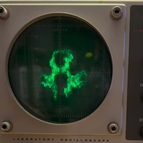
the end result sounds a lot more like the song than the buzz does. it isn't the song: you can hear the drawing in it, and the cleaner you want the picture, the more you hear it.
every scope shot is the real scope, filmed off the screen, and the sound in the video is the exact file that went into it, not a room mic.
part 8 · What does it sound like? · coming soon
what came out of it
the encoder from part 8 turned into the scope tool, on this site. it runs in your browser and nothing gets uploaded. give it a song (or a MIDI file) and a picture, an image or a short video, and it makes stereo audio that draws the picture on an xy scope. there's the all-pass mode with the audio ↔ picture slider, the plain drawing (the buzz), drawing at the bassline's pitch, and MIDI, where the notes set the trace rate. the "bad apple" button loads 20 seconds of it in three versions: the song drawing it, the buzz, and melody drawing.
what's next
the scope still has its old capacitors, apart from the one i replaced, and it still glitches when it's warm. so a full recap is due, and freeze spray or a bit of heat should help find whatever is failing when it heats up.
credits
- BilliumMoto's bad apple oscilloscope writeup, on tracing the picture at each note's pitch.
- the bad apple MIDI is from the badapple-midi project (PGFLIMSXD, nlexsctex, handhule90).
- "bad apple!!" is alstroemeria records' arrangement (vocals: nomico) of a touhou project song by zun. the shadow-art video is by anira.
- doom's level data is from id software's shareware release. tennis for two was made in 1958, for an oscilloscope.
- and everyone in the comments: the theories, the "but can it play doom", the "now play bad apple". that's how this series got here.
Episodes
- 01Why won't this old scope work?
A 1960s Heathkit IO-12 lab scope that shows no trace at all. The rear fuse is blown, and fuses blow for a reason, so the case comes off to see the 5-inch CRT and the tubes.
- 02The dim bulb tester
I built a dim bulb tester, a 60 W bulb in series with the scope. The bulb stays bright and only 9.3 V reaches the scope, so there is a dead short somewhere after the power switch.
- 03The short, the fix, and the one dark tube
A paper capacitor leaking tar was the dead short. I cut it out and fitted a new one. The pilot light comes on, but the screen stays blank and one tube doesn't light.
- 04The wrong tube
Socket V9 should hold a 1V2, the rectifier for the CRT's high voltage, but someone had put a 12AU7 there. With a real 1V2 in, a dot appears and it reacts to my guitar, but the trace is only a line.
- 05It only works sideways
The sweep starts working, and my guitar's signal shows up, but only with the scope on its side. Stand it up and it collapses back into a line. My best guess at the time was the stuck frequency selector.
- 06It finally works upright
Under the circuit board, a terminal strip in the sweep circuit was missing the screw that grounds it. A soldered jumper to the next grounded strip fixed it, and it works right side up.
- 07XY mode, and Bad Apple
I forced the seized selector to EXT INPUT, which unlocks XY mode: the left audio channel moves the beam sideways and the right moves it up and down. Then the scope plays Tennis for Two, Doom and Bad Apple.
- 08What does it sound like?
The signal that draws Bad Apple is just a buzz. Two ways to make it sound more like the song: trace the picture at the pitch of each melody note, or start from the song and shift its pitches in time until it draws.
links coming